

What Is Stack Pointer And Program Counter 16 Bit Registers
Embedded Systems - Registers
Registers are used in the CPU to store information on temporarily basis which could be data to be candy, or an address pointing to the data which is to exist fetched. In 8051, there is i information type is of 8-$.25, from the MSB (most significant scrap) D7 to the LSB (to the lowest degree significant bit) D0. With 8-bit information type, any information type larger than 8-bits must exist cleaved into 8-scrap chunks earlier information technology is processed.
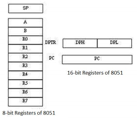
The nigh widely used registers of the 8051 are A (accumulator), B, R0-R7, DPTR (data pointer), and PC (programme counter). All these registers are of viii-$.25, except DPTR and PC.
Storage Registers in 8051
We volition talk over the following types of storage registers hither −
- Accumulator
- R annals
- B register
- Data Arrow (DPTR)
- Program Counter (PC)
- Stack Pointer (SP)
Accumulator
The accumulator, register A, is used for all arithmetics and logic operations. If the accumulator is not present, then every outcome of each adding (improver, multiplication, shift, etc.) is to be stored into the main retention. Access to main memory is slower than access to a register like the accumulator because the technology used for the large chief memory is slower (but cheaper) than that used for a annals.
The "R" Registers
The "R" registers are a fix of viii registers, namely, R0, R1 to R7. These registers function equally auxiliary or temporary storage registers in many operations. Consider an example of the sum of 10 and 20. Store a variable 10 in an accumulator and some other variable twenty in, say, register R4. To procedure the add-on performance, execute the post-obit command −
ADD A,R4
After executing this instruction, the accumulator will contain the value thirty. Thus "R" registers are very important auxiliary or helper registers. The Accumulator lone would not be very useful if it were not for these "R" registers. The "R" registers are meant for temporarily storage of values.
Allow usa take another example. We will add the values in R1 and R2 together and then subtract the values of R3 and R4 from the event.
MOV A,R3 ;Move the value of R3 into the accumulator ADD A,R4 ;Add the value of R4 MOV R5,A ;Store the resulting value temporarily in R5 MOV A,R1 ;Move the value of R1 into the accumulator ADD A,R2 ;Add the value of R2 SUBB A,R5 ;Subtract the value of R5 (which now contains R3 + R4)
Every bit yous tin see, we used R5 to temporarily concur the sum of R3 and R4. Of course, this is not the most efficient fashion to calculate (R1 + R2) – (R3 + R4), just it does illustrate the use of the "R" registers equally a way to store values temporarily.
The "B" Register
The "B" register is very similar to the Accumulator in the sense that it may agree an 8-scrap (one-byte) value. The "B" register is used simply by ii 8051 instructions: MUL AB and DIV AB. To speedily and hands multiply or split up A by another number, you may store the other number in "B" and make employ of these two instructions. Apart from using MUL and DIV instructions, the "B" register is oft used as yet some other temporary storage register, much like a ninth R register.
The Data Pointer
The Data Arrow (DPTR) is the 8051's merely user-accessible xvi-bit (two-byte) register. The Accumulator, R0–R7 registers and B annals are 1-byte value registers. DPTR is meant for pointing to data. It is used by the 8051 to access external memory using the address indicated by DPTR. DPTR is the only 16-bit register bachelor and is oftentimes used to shop ii-byte values.
The Program Counter
The Program Counter (PC) is a 2-byte address which tells the 8051 where the side by side didactics to execute tin be constitute in the memory. PC starts at 0000h when the 8051 initializes and is incremented every time after an instruction is executed. PC is not e'er incremented by 1. Some instructions may require 2 or three bytes; in such cases, the PC volition exist incremented by ii or iii.
Branch, leap, and interrupt operations load the Programme Counter with an address other than the next sequential location. Activating a power-on reset will cause all values in the register to be lost. It means the value of the PC is 0 upon reset, forcing the CPU to fetch the outset opcode from the ROM location 0000. It means we must place the first byte of upcode in ROM location 0000 because that is where the CPU expects to find the first teaching.
The Stack Arrow (SP)
The Stack Pointer, like all registers except DPTR and PC, may hold an 8-scrap (i-byte) value. The Stack Arrow tells the location from where the next value is to be removed from the stack. When a value is pushed onto the stack, the value of SP is incremented and then the value is stored at the resulting retention location. When a value is popped off the stack, the value is returned from the memory location indicated past SP, and then the value of SP is decremented.
This order of operation is of import. SP will exist initialized to 07h when the 8051 is initialized. If a value is pushed onto the stack at the aforementioned time, the value will be stored in the internal RAM address 08h because the 8051 will first increment the value of SP (from 07h to 08h) and then will store the pushed value at that retentiveness address (08h). SP is modified directly past the 8051 by vi instructions: Button, POP, ACALL, LCALL, RET, and RETI.
ROM Space in 8051
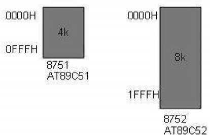
Some family unit members of 8051 have merely 4K bytes of on-flake ROM (e.g. 8751, AT8951); some accept 8K ROM similar AT89C52, and there are some family members with 32K bytes and 64K bytes of on-fleck ROM such as Dallas Semiconductor. The point to remember is that no member of the 8051 family unit tin access more than 64K bytes of opcode since the program counter in 8051 is a 16-bit register (0000 to FFFF address).
The first location of the plan ROM within the 8051 has the address of 0000H, whereas the last location can be different depending on the size of the ROM on the chip. Among the 8051 family members, AT8951 has $one thousand bytes of on-scrap ROM having a memory address of 0000 (kickoff location) to 0FFFH (last location).
8051 Flag Bits and PSW Register
The program condition word (PSW) register is an 8-flake register, likewise known as flag register. Information technology is of 8-bit wide but only vi-bit of information technology is used. The two unused $.25 are user-defined flags. Four of the flags are chosen conditional flags, which means that they betoken a condition which results after an education is executed. These four are CY (Behave), AC (auxiliary acquit), P (parity), and OV (overflow). The bits RS0 and RS1 are used to modify the depository financial institution registers. The post-obit figure shows the program status discussion register.
The PSW Annals contains that status $.25 that reflect the current status of the CPU.
| CY | CA | F0 | RS1 | RS0 | OV | - | P |
|---|
| CY | PSW.seven | Carry Flag |
| Air-conditioning | PSW.six | Auxiliary Deport Flag |
| F0 | PSW.5 | Flag 0 available to user for general purpose. |
| RS1 | PSW.4 | Register Bank selector bit 1 |
| RS0 | PSW.iii | Annals Depository financial institution selector bit 0 |
| OV | PSW.2 | Overflow Flag |
| - | PSW.1 | User definable FLAG |
| P | PSW.0 | Parity FLAG. Set/ cleared by hardware during instruction cycle to indicate fifty-fifty/odd number of 1 bit in accumulator. |
We tin select the corresponding Annals Depository financial institution chip using RS0 and RS1 bits.
| RS1 | RS2 | Register Depository financial institution | Address |
|---|---|---|---|
| 0 | 0 | 0 | 00H-07H |
| 0 | one | one | 08H-0FH |
| ane | 0 | two | 10H-17H |
| 1 | 1 | 3 | 18H-1FH |
-
CY, the carry flag − This carry flag is set (1) whenever at that place is a carry out from the D7 bit. It is affected subsequently an 8-bit improver or subtraction performance. Information technology tin can too be reset to 1 or 0 directly by an instruction such as "SETB C" and "CLR C" where "SETB" stands for set bit carry and "CLR" stands for articulate carry.
-
Air-conditioning, auxiliary carry flag − If there is a conduct from D3 and D4 during an ADD or SUB operation, the Air-conditioning bit is set; otherwise, it is cleared. It is used for the instruction to perform binary coded decimal arithmetic.
-
P, the parity flag − The parity flag represents the number of 1's in the accumulator register merely. If the A register contains odd number of 1's, then P = 1; and for even number of 1'due south, P = 0.
-
OV, the overflow flag − This flag is set whenever the result of a signed number performance is likewise big causing the loftier-order bit to overflow into the sign bit. Information technology is used only to detect errors in signed arithmetics operations.
Example
Show the condition of CY, AC, and P flags after the addition of 9CH and 64H in the following education.
MOV A, #9CH
Add together A, # 64H
Solution: 9C 10011100 +64 01100100 100 00000000 CY = 1 since there is a conduct beyond D7 bit AC = 0 since there is a carry from D3 to D4 P = 0 because the accumulator has even number of 1'southward
Useful Video Courses

Video

Video

Video

Video

Video

Video

What Is Stack Pointer And Program Counter 16 Bit Registers,
Source: https://www.tutorialspoint.com/embedded_systems/es_registers.htm
Posted by: haughtyountop.blogspot.com
0 Response to "What Is Stack Pointer And Program Counter 16 Bit Registers"
Post a Comment